(1) Full discharge The test object must be completely discharged before testing. When the measured object has an interference voltage, the "E" terminal must be grounded and then connected.
(2) Connection mode:
There are two lengths of the test wire, one end of the red plug of the length measurement line is plugged in the “L†end, and the black plug is plugged in the “G†end; the short end of the test lead is connected to the “E†end. The other ends of the two test leads are respectively connected to the corresponding ends of the device under test.
(3) Turn on the instrument:
Connect the power cord, turn on the switch, and the main menu appears on the screen:
WELCOMETOUSE
ZOBSERISE
VER2.00.5KV
Z-ELECCO. ,LTD
2. Parameter test:
A. Voltage selection Press the "+" key in the main menu to cycle through the desired voltage.
B. Insulation resistance test Press the "Measuring" button to test, press the measurement time as the reference "0", wait about 5 seconds, you can complete the insulation resistance test at 0 seconds, this time the screen shows:
XX/XX/XXXX;XX;XX
(year, month, day, minute, second)
R00S=XXXXX.XX.MΩ
Wait for the absorption ratio to test.
If no absorbance test is performed, press the reset button to exit. As the circuit board is equipped with a large capacity anti-interference, its charging causes the sampling error of the insulation resistance, so that the insulation resistance value of 0 seconds is too large. Therefore, generally take 15 seconds resistance value.
C. Absorption Ratio Test The measurement of B is continued, and the measurement is started at the timing of B. At 15 seconds, the resistance R15S at 15 seconds is automatically measured, and the lock is displayed on the second line. Then take measurements every 15 seconds and display them in the second row. Then take a measurement every 15 seconds and display it in the third row.
When 60 seconds, the resistance value R60S at the time of 60 seconds is automatically measured, and the lock is displayed on the third row. At the same time, the absorption ratio is calculated and displayed on the left half of the first row. The screen display changes to:
K=X. XXXX;XX;XX
R15S=XXXXX. XXMΩ
R60S=XXXXX. XXMΩ
Continue to wait and enter the polarization index test state.
If you exit, press the reset button to retest.
D. Measurement of Polarization Index Following B and C, the polarization index was measured, and measurements were taken every minute from the beginning of 2 minutes. Accordingly, in the fourth row, the resistance values ​​R02m, R03m------ were displayed.
When measured for 10 minutes, the insulation resistance value R10m is locked in the fourth row, and the polarization index PI is automatically calculated and displayed on the right side of Dijon. The screen appears as:
K=X. XXPI=X. XX
R15S=XXXX. XXMΩ
R60S=XXXX. XXMΩ
R10S=XXXX. XXMΩ
At this time, a measurement process is over, the internal high pressure of the instrument is automatically cancelled, and the internal buzzer sounds long, prompting the end of the measurement process.
3. Time modification:
The instrument has a real-time clock display and does not affect timing even if it is turned off. When it is necessary to modify the time, it must be done in the state that the main menu is displayed on the screen just after power-on or when the reset button is pressed.
Hold down the "" key, this time on the first line of the screen shows:
XX/XX/XXXX:XX:XX
(year, month, day, minute, second)
The third line shows:
MODIFYTIME
(Press â†, +, - key for time modification) "→" is used to select a certain period of time, press "→" key, the cursor is shifted to the right, "+" and "-" are used to add or subtract values, after modification, press Press “â†â€ key to save the modified value and perform the time modification. In this measurement process, pressing →, +, - does not affect the time display, just press “→†after power on or reset to enter the time. modify.
Derrick 313 Pwp Shaker Screen
Replacement PWP Screens for Derrick 313 Shakers
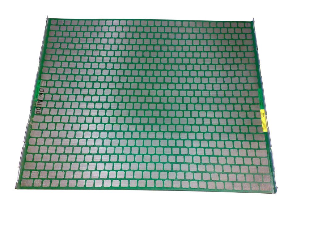
SJ-Derrick 313 PWP Shaker Screen is designed for the replacement screen of Derrick 313M shale shaker. There is an operating handle on one side of the screen and a triangle breach in the center of the opposite side. Thanks to he machine assembled backside seal rubber, even the strip appears a small broken part, the other parts will be steady on back panel still. The most obvious advantage of PWP screen is better resistant to oil. And mesh sizes are commonly available from API 40 to API 270.
Technical Parameter
- Material: stainless steel 304/316/316 L.
- Construction Type: PWP (perforated wear plate).
- Wear Mesh Shape: rectangle.
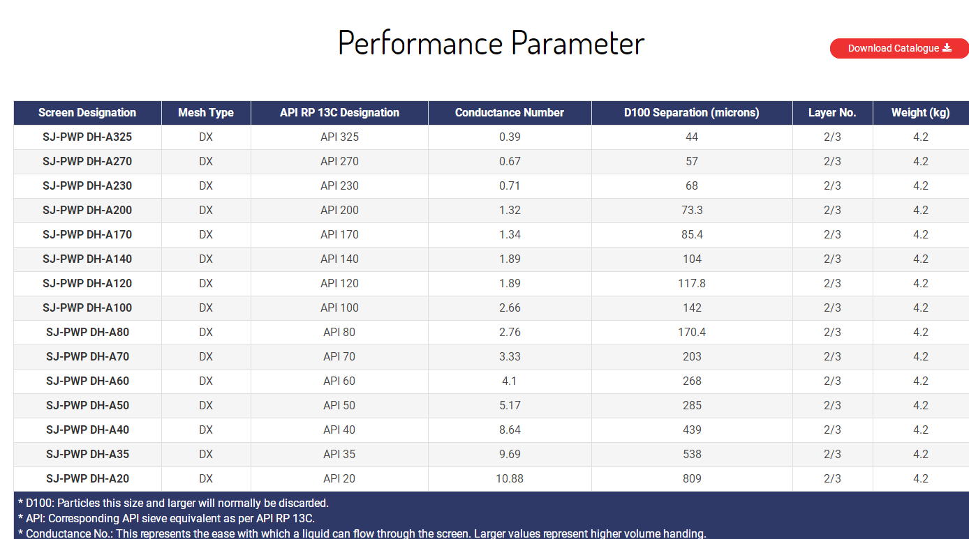
- API RP 13 C Designation: API 20 – API 325.
- Series: DX, DF, HP optional.
- Color: green.
- Package: 2 pcs per carton, 20 pcs/wooden case.
Adaptable Shale Shaker Model
SJ- Derrick 313 PWP shaker screen are used as the substitute screen for
- Derrick 313 4-panel shaker.
- Derrick Triple 313 shaker.

Remarks:
Derrick 313, PWP, DX, DF, HP are marks of Derrick Corporation.
ShengJia only produces the replacement screens but not original from Derrick.

Derrick 313 Pwp Shaker Screen,Derrick 313 Shaker Screen,Derrick 313 Shale Shaker Screen ,Derrick 313 Pwp Shaker Screen
Anping Shengjia Hardware Mesh Co.,ltd , https://www.oilshakerscreen.com
