
The application of the solder joint counting system fundamentally solves the problem of leakage spot of resistance spot welding, improves the process control capability, provides a strong guarantee for controlling the strength of the white body, and changes the current situation of increasing the number of inspectors to improve the quality. Save labor costs.
Resistance spot welding plays an important role in the automotive industry. When automatic robotic welding is not fully realized, a large amount of manual welding is required. However, due to the randomness of manual operation, leakage and leakage welding sometimes occur. To solve this problem, it is necessary to add a large number of quality personnel to inspect and inspect the operation of spot welding. In order to change this situation, the technicians in the welding shop of Chery Automobile Co., Ltd. explored a good way to control the spot resistance spot welding in the production process - the development of a solder joint counting system suitable for white body welding.
Solder joint counting system
1. Hardware design of solder joint counting system
(1) Hardware system components
The hardware of the solder joint counter is mainly composed of six parts: power supply, signal acquisition, central processing unit, display, execution and network topology. The signal acquisition part uses photoelectric coupling to separate the voltage and protect the central processing unit. The central processing unit adopts the MCS-51 series compatible AT89S single-chip microcomputer, which has low power consumption and high reliability. In the display part, the LED digital tube commonly used in industrial control is used. Display components with reliable performance.
In the design process of this hardware, the modular design makes full use of existing resources to achieve the functions we want. This modular design makes it easier to generalize this solder joint counter to actual production.
(2) Power module design
The counter is powered by the 24V AC power supply provided in the welding machine. The power module rectifies, filters and regulates it to provide a 5V regulated power supply for the central processing unit. Figure 1 is a circuit diagram of the power supply.
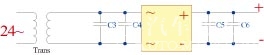
Figure 1 Circuit diagram of the power supply
(3) Design of the main part of the system (solder counter)
The solder joint counter is mainly composed of a data acquisition module, a central processing unit (CPU) and an execution part.
a. Data acquisition module
The data acquisition module consists of a current sensor and a data acquisition circuit. During the spot welding operation, the welder cable generates a large current, and the current sensor detects the generation of such current to judge the spot welding operation. The signal of the sensor is converted into a digital signal by a signal acquisition circuit and transmitted to the central processing unit.
b. Central processing unit
This system adopts Atmel's AT89S system single-chip computer commonly used in industry. It has the advantages of strong anti-interference, low power consumption and low cost. It is more suitable for production site applications, and it has rich on-chip resources for future systems. The upgrade provides the conditions.
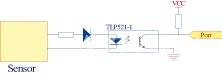
Figure 2 signal acquisition circuit
Wardrobe Closet,Customized Closet,Sliding Door Wardrobe
UV Boards,Wardrobes Co., Ltd. , http://www.wall-board.com