
[Abstract] Some techniques and methods for quickly implementing product structure design in Pro/ENGINEER software are introduced. If it can be used flexibly, it can greatly accelerate and optimize product design.
ã€Key words】 Pro/ENGINEER Copy Features Product design
Nowadays, the competition of products, especially the competition of consumer electronic products, is becoming more and more fierce. How to shorten the development cycle of products and timely launch new products suitable for the market has become a common concern of major companies. Pro/ENGINEER software has been widely used in product development and design with its powerful modeling and structural design functions, providing conditions for effectively shortening the product development cycle. However, if we can effectively master some of the advanced features and techniques of Pro/ENGINEER software, we will achieve better results than expected.
In the product development process, we will find that most products are approximate symmetrical structures; or there are many identical or similar features in the same product; or because of product serialization, the same products have been the same or similar Structure. For these features, we don't have to go through the design of its size structure step by step. This article will show you how to quickly replicate these features in Pro/ENGINEER 2001 to greatly accelerate and optimize our product design.
1 feature image
When designing our products, most of them are symmetric structures. At this time, we can easily copy the other half features with the image command. The specific operation is “Feature→Copy→Mirror→Independent/Dependent→Select the feature to be mirrored→Select or create mirror planeâ€.
2 mirror geometry
Sometimes we need to mirror the entire model when we need to mirror the entire model. That is: "Features → Mirror Geom → Select or Create Mirror Plane". Of course, to complete the mirroring of the entire model, you can also use the feature mirroring command described above, namely: "Feature" → Copy → Mirror → All Feat → Independent / Dependent (Dependent) → Select or create a mirror plane. The difference between the two is mainly.
(1) The features produced by the mirror geometry are considered to be one. Only one feature is generated in the model tree. The size is completely dependent on the original model. It is not possible to delete only one feature. When mirroring all features, it is equal to the original number. Features that can be modified or deleted individually.
(2) When mirroring all features, and then using the Insert Mode function to return to the new feature before the Copy action, this feature is not copied with the image unless the Mirror Geom method is used.
3 feature movement
We can also select a feature in the model for translation or rotation replication. The specific steps are: “Feature→Copyâ€â†’Move→Independent/Dependent→Select the feature to move→Translate/Rotate→Define pan or rotate The direction and size of the movement → define the size that the feature needs to change."
4 array
Arrays are also the most common way we copy features.
(1) For the same array of examples, we can easily grasp it, namely: Feature→ Pattern→Select the features to be arrayed→ Identical→Select the size of the array in the first direction and enter the size increment → Enter the number of arrays in this direction → select the size of the array in the second direction and enter the size increment → enter the number of arrays in this direction.
(2) Sometimes the size of the instance varies with the array, then we have to choose the array property as Varying.
(3) When there may be different changes in the shape of the instance and they may intersect each other, we have to select the array property as General.
(4) For arrays with multiple features in succession, we must first make them into a local group, and then use the steps of “Feature→Group→Pattern†to perform the array.
(5) For a circular array, the dimension of the guiding feature must have an angular dimension. If you cannot create an angular dimension, you can use the Copy→Move→Rotate method to rotate a feature first and then perform an array. You can also create an angular dimension by creating a datum plane.
(6) Sometimes you can refer to the existing array in the model, that is, select the feature to be arrayed in the feature tree, right click, and select “Pattern→Ref Pattern†to quickly complete the same size as the previous one. Array.
5 array table
With the array table, the position of the instance can be controlled by creating an absolute size for the same reference as a guide. You can enter dimensions in tabular form and edit the dimensions of each instance individually. Individual instances can be removed from the array by removing the entry from the table. This approach has greater flexibility because more complex instance combinations can be created with unequal or irregular sizes. Array tables should be considered for use in the following situations.
(1) The incremental size control array cannot be used because it is too complicated or irregular.
(2) The design intent requires that each instance be located for the same reference, rather than incrementally positioning the previous instance.
(3) Multiple models must share the same array.
(4) Multiple array forms need to be created for different variations of the model.
To create an array with an array table, the general steps are: Feature → Pattern → Select Features to Array → Table → Select Drive Size → Done → Add / Read ) Array table. It is also possible to convert a size-driven array into an array-driven array. The general steps are: Feature→Redefine→Select an Array Feature→Pattern→ To Table→Input Array List name → Done/Return. The array will now be driven by the array table, and Pro/ENGINEER automatically changes the labeling scheme to make it non-incremental. You can edit the array table using Modify→Pattern Table.
6 part family
When we want to build a series of very similar parts, we can use the settings of the part family. When setting up a part family, you must first create a reference part, which is called the Generic Model here, and then set the part family form, and the part produced by the Generic Model is called Instance. The specific steps are: Family Tab → insert a new instance in the selected row → add / delete table columns → define a changeable size or define a selective feature.
7 feature library
User-Defined Feature is a feature group used to copy the same shape. It requires us to define some features that are often used in product design as UDFs according to the characteristics of the company's own products. It is convenient to be called in future product design, which greatly improves the speed of product development and design. The completion of the UDF feature is generally divided into two steps. The first is the establishment and definition of the UDF. The steps are: Feature→UDF Library→Creature→Enter UDF Name→Select UDF Property(Stand Alone / Subordinate ) → Select the feature to be added to the UDF → the reference prompt when the input feature is placed → define Var Elements or Var Dims as needed; the second is the placement of the UDF, the steps are: Feature → Creature →User Defined→Select the UDF file name to be placed→Specify the placement option (Independent/UDF Driven)→Specify the Scale and specify the display options→ Follow the prompts to select the placed reference.
8 Feature library with part families
This is a comprehensive application of two advanced command part families and feature libraries. In the process of building the feature library, we sometimes find UDFs used in a series of products, but the size and number of features are slightly different, and the shapes are exactly the same. At this time, it is very convenient to use the part family when defining the UDF. . The process of establishing it is similar to the process of establishing the feature library described above, except that after the elements in the feature definition dialog are all defined, select the option Family Table→Define, and then according to the above description. The method of defining the part family is done. When placing a UDF, after selecting the UDF file name, the Instance option will appear, let us choose the Instance to be placed.
9 Copying of features in the same model
In the process of creating the model, sometimes the subsequent feature shape is exactly the same as the previous feature, except that the individual dimensions and references of the feature are slightly different, so we can copy in the same model. The establishment process is: Feature→Copy→Same Refs→Independent/Dependent→Select the feature to be copied→Define the size to be modified. If you select New Ref, you can redefine the related faces of the copied features, reference faces, dimension references, and so on. In addition, we can also copy features on the same model but on different file storage versions, ie select From Dif Vers (different versions) when copying features, the build process is somewhat similar to the replication of the different model features described below.
10 replication of features between different models
Relative to the replication of features in the same model, we can also replicate features between different models, directly using the features that were created in the previous model, which is somewhat similar to UDF features. The establishment process is: Feature→Copy→New Refs→From Dif Model→Independent→Select the model to be copied or select the feature to be copied→Setting Proportion → Select the highlighted reference that appears in the reference model in the new model.
11 Copying features with surfaces
When copying a feature using a surface, first copy the surface of the feature you want to copy into a surface, then use the Feature→Create→ Surface→Transform→Move/Mirror. The operation completes the copy, copies the surface features, and finally copies the surface in the generated entity. We often use surface copy features, then translate or rotate the surface, then perform arrays and finally generate solids to avoid over-characteristics.
We also often use surfaces to mirror the entire model by first copying the entire model into a surface, namely Feature → Create → Surface → Copy → Solid Surface → Select Model. Then convert the surface and copy the surface without copying, ie: Surface → Transform → Mirror → No Copy → select the surface to be mirrored → select or create a mirror plane. In this way, similar to the mirror geometry, the entire model can be mirrored. The main difference is that all features in front of the mirror geometry copy, including datum planes, coordinate systems, and surface features, etc., while using surface features to copy features, only mirrors Copy the entity characteristics.
12 Generate symmetrical parts in the assembly drawing
If the two parts to be designed are completely symmetrical, we can copy one part in the assembly drawing to create another part that is symmetrical. The operation is: Component → Create → part → Mirror → select the part to be mirrored → select or create a mirror plane.
Some of the quick structural design methods described above, if properly applied, can greatly increase the speed of our product design. In the design process, we should try to use some of the same references, so that when copying features, we can avoid choosing too many feature placement references. The front and rear covers of the 29-inch color TV shown in Figures 1 and 2 are applied to most of the quick design methods described above during the structural design process, so that the overall structural design time can be shortened by about 1/3.
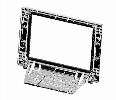
Figure 1 color TV front frame
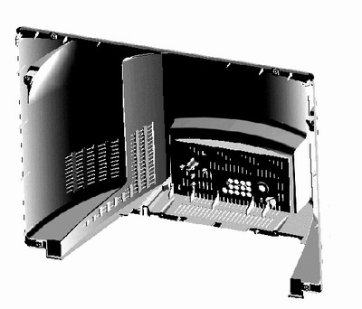
Figure 2 color TV back cover
In addition, in the process of structural design, we not only consider designing the structure of the product, but also need to consider the least feature, adopt the simplest method, and also need to consider which features need to be associated and which features are not related. It is convenient for future design changes, because such design changes are often indispensable.
We are factory which specializing producing and distribute hot melt Glue Guns. Main category include 10W, 20W, 40W,60W,100W,200W, 250W with cord and cordless glue guns. All glue guns been GS,CE,KTC, SAA, CSA,INMETRO approval.
Our Professional Glue Gun designed for many applications. Fastening various materials such as paper, cardboard, fabric,wood, lace,trims,leather,metal,glass, tiles, rubber, ceramics and flooring etc. Ideal for hobby and household repair,DIY craft projects.
High Quality Hot Melt Glue Gun
Glue Guns, Industrial Glue Gun, Hot Melt Glue Gun, Silicone Glue Gun
Ningbo Kingvos Electrical Appliance Co.,Ltd , http://www.kingvos.com