
The smart pixel-based design approach provided by CAXA Entity Design can modify the entire design by dragging the dimensions of the smart pixels. But for a part may need to be composed of a lot of smart pixels, then it is too much trouble to modify the size of each pixel. Sometimes a design part we want to be able to modify several major dimensions to create a new part series. To solve these problems, you need to use parameterization and build a parameterized library.
For example, we need to design a series of drawers like the one below, and we hope to define the drawers of the series with only two parameters: height a, rounded corner r, and wall thickness t. The conditions are width = 4*a, depth = 3*a, and wall thickness = t.
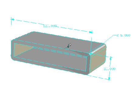
1) First design the basic shape of the drawer. Drag a box and define the dimensions: length = 20, width = 80, height = 60 Drag into a hole type of the box, define length = 10, width = 70, height = 55.
2) Define the parameters in the smart pixel state. Select the box to enter the smart pixel editing state, right click and select "Parameter". From the pop-up parameter list, select Add Parameter. Enter the parameter name a and the value 20 respectively. "determine". The same method increases the parameter b, the value 80. Parameter c, value 60.
3) With the method of the second step, select the hole type cuboid to enter the intelligent pixel editing state, and increase the parameters a1=10, b1=70, and c1=55.
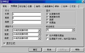
4) Associate the parameter with the feature size of the smart pixel. Select the box to enter the smart pixel editing state, right click and select "Smart Element Properties". Select "Bounding Box". Select "Show formula" in the lower left corner of the bounding box column, and change to a, b, c in the columns of length, width and height above. "determine".
5) As in the method of step 4, the length, width, and height of the associated hole-like cuboid are a1, b1, and c1.
6) Define the rounding transition parameter r. Select the box to enter the smart pixel editing state, right click and select "Parameter". Increase the parameters r1=5 and r2=5. "determine"
7) Select the box to enter the smart pixel editing state, right click and select “Smart Element Propertiesâ€. Select "Tilt".
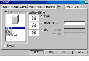
8) Select the display formula. Select the starting edge separately, fillet radius = r1, then select the side edge, fillet radius = r2.
9) Define the parameters of the part and associate them with the parameters of the smart pixel. Click the drawer to enter the part editing state, right click to select the parameter, increase the parameter t=5, r=5. "determine".
10) In the parameter table status, check "Show all parameters of the selected pixel below". And fill in the following expression in the "Expression" column: b = 4 * a, c = 3 * a,, r1 = r, r2 = r
A1=(a – 2*t), b1=(b - 2*t), c1=c – t
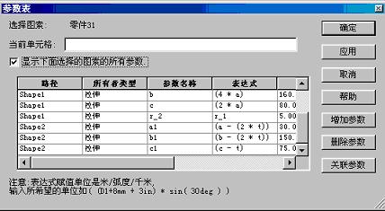
11) Turn off all the parameters of the display pixel, only the three parameters a, r, t are left in the parameter table. Enter a different number of drawers by entering different parameters in the Value field.

Steel Coil,Steel Sheet,Stainless Steel Sheet
Hong-Steel Co., Ltd. , http://www.qiyistainlesssteel.com