1. Processing characteristics with shoulder nut
The shoulder stainless steel nut blank is shown in Figure 1. It is a large-volume part produced by our company, with an annual output of more than 10,000. However, such parts are relatively small in size and short in processing time. The operator needs to repeatedly clamp during the processing on the ordinary horizontal lathe, which leads to an increase in the auxiliary time of the processing, an increase in labor intensity, and a low processing efficiency. In order to improve the processing efficiency and reduce the labor intensity, the processing technology is improved on a CNC lathe.
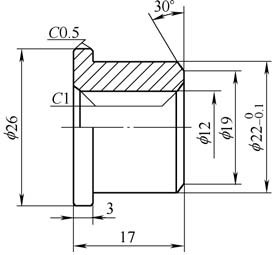
figure 1
2. Process improvement
The general horizontal lathe processing such a shoulder nut is as follows: 1 preparation, quenching and tempering. 2 car end face, outer circle, drilling, chamfering and cutting. 3 Turn the other end of the car to the total length, chamfer, tapping.
It can be seen from the above process that the production of such a workpiece by an ordinary horizontal lathe requires two clamping operations, which is complicated in operation and low in efficiency.
Improve the processing technology, transplant the process completed on the ordinary horizontal lathe to the CNC lathe, as shown in Figure 2, the CNC car process is: 1 preparation, quenching and tempering. 2 The entire shape, length, end face and chamfer are completed at one time. 3 The fitter taps the thread with a vertical drill.
figure 2
The biggest advantage of the CNC lathe is that it can complete the machining of 3 pieces of workpiece every time, and the threading of the lathe is passed by the fitter through the vertical drilling machine. It can be seen that the new process can indeed improve production efficiency, reduce production costs and reduce labor intensity.
3. CNC machining
CNC machining is the core of this process improvement, mainly optimized for CNC programming. In programming, the M00 pause function is used, the command M98 is used to call the subroutine function, and the workpiece coordinate system function is positioned by G54, G55, G56 to achieve the purpose of multi-piece machining. CNC machining is divided into the following processes:
(1) Clamping. Before programming, you must choose a reasonable clamping method. Because it is bar blanking processing, the fixture selects the three-claw self-centering chuck that comes with the lathe. The clamping method is shown in Figure 3. The bar should extend 70mm outside the three-claw self-centering chuck (this is the position of the main program G54G00X19Z0.2, and then the blank end face can be clamped by the flat tool) .

Figure 3 clamping method
(2) Numerical control programming. Programming uses the main program plus the call subroutine method to achieve multi-piece processing. First, you need to set the workpiece coordinate system. The workpiece coordinate system is set as shown in Figure 4. The origin of the workpiece coordinate system G54 is X0 Z0, which is used for the processing of the first product. The origin of the workpiece coordinate system G55 is X0 Z-20.6, which is used for the processing of the second product. The origin of the workpiece coordinate system G56 is X0Z-41.3, which is used to process the third product.

Figure 4 Setting of the workpiece coordinate system
The next step is to write a CNC machining program. The CNC machining program is divided into two parts:
1 main program, the main function is the workpiece extension length tool setting, pause, select the workpiece coordinate system and call the subroutine. 2 subroutine, the main function is the processing of individual part contour, inner hole and chamfer. The program code is as follows.
Main program: O0176 (program number)
N1 G99
N2 T0101 (outer round knife pairing)
N3 G54 G00 X19 Z0.2
N4 M00 (suspended)
N5 G00 X100
N6 M00 (suspended)
N7 G54 M98 P0175
N8 G55 M98 P0175
N9 G56 M98 P0175
N10 M30
Subroutine: O0175 (program number)
N1 G99
N2 T0101 (outer round knife)
N3 M03 S800
N4 M08
N5 G00 X30
N6 Z0
N7 G01 X5 F0.2
N8 X1 F0.1
N9 X-2 F0.05
N10 G00 X24
N11 G01 Z-14 F0.2
N12 X25
N13 G00 Z0
N14 G01 Z-1.5 X22 F0.15
N15 Z-14 F0.25
N16 X24.5
N17 Z-14.9 X26
N18 Z-21
N19 G00 X100
N20 Z200
N21 T0303 (Drilling)
N22 M03 S300
N23 G00 X0
N24 Z2
N25 G01 Z-3 F0.1
N26 G74 R0.5
N27 G74 Z-22 Q8000 F0.1
N28 G00 Z200
N29 T0202 (Chamfering Knife)
N30 M03 S500
N31 G00 X12
N32 Z1
N33 G01 Z-1 F0.1
N34 G00 Z300
N35 T0404 (cutting knife)
N36 M03 S800
N37 G00 X28
N38 Z-20
N39 G01 X25 F0.05
N40 X26
N41 Z-19
N42 X25 Z-20
N43 X10
N44 G00 X100
N45 Z200
N46 M05
N47 M09
N48 T0101
N49 M99
(3) Pair of knives. The tool setting is a key step in CNC machining. The accuracy of the tool directly determines the quality of the product. The reserved length for clamping is 70mm. In fact, this length is not measured. This is the position of the main program G54G00X19Z0.2. The specific implementation method is to adjust the first workpiece programming origin to (X0, Z70). When the operator presses the start button, the main program runs, the machine tool moves quickly to the coordinate system G54 (X19, Z0.2), and the program pauses. At this time, the distance from the three-jaw self-centering chuck is just 70mm. The operator can directly pull the bar out of the tool and touch it on the tip. Then press the start button to make the X-axis direction deviate from the workpiece by a distance greater than the diameter direction (ie, the main program G00X100 tool offset does not affect the clamping), the program pauses, clamping the three-jaw self-centering chuck workpiece. Press the start button again to start machining the first part. The second and third parts are automatically machined. After a set of parts is finished, press the start button again, the machine returns to the tool setting point of the first part, and the next set of tool sets is started, and the cycle is repeated accordingly. The bar processing method can avoid the error caused by the operator's measurement, ensure the processing quality of the product, fast clamping speed and high efficiency.
4. Conclusion
Before the process improvement, it takes 4 minutes to machine a blank with a shoulder nut on a conventional horizontal lathe. After the process is improved, it can be processed every 3 minutes on a CNC lathe.
It can be seen that after the process improvement, the efficiency is increased by more than 50%, and the labor intensity is lowered, and the product qualification rate is also improved, which is highly praised by the operator. In fact, this optimized programming technology can be applied in vehicle processing. In the machining of the car, when the precision of the parts is high and the axial length is small, the machining method can be used, and more pieces can be processed at one time. For production units based on small parts processing, it is more practical in bar processing. This process has been proven in the processing of many products.
Cutting
mode: Laser cutting
Suit
material: carbon steel, alloy steel, galvanized plate, stainless steel, copper
plate, aluminium plate, steel tube, copper pipe, aluminium pipe etc. sheet
matal.tube stock.
1.Product describe
Fast
cutting spead, high working efficiency and high stability, it is a high-tech
equipment that set one of fiber laser technology, CNC technology and high-tech
equipment.
2. Product features
Imported
with original packaging servo motor and reducer, bilateral drive, high
operating speed and high precision.
Can
remote operation, convenient and efficient, save labor.
Imported
cutting head, optical glass, focusing is convenient and cutting perfect.
Fiber
transmission, no need to adjusted the optical circuits, focal spot is more
smaller.
Adopted
auto lubrication system, auto dual-temperature control syatem, convenient and
efficient.
High
precision grinding guide rail, gear and rack, precision class up to ±0.02mm.
3.Product
parameters
|
Type
|
TI-3015
|
|
Effective
cutting width ( mm)
|
1500
|
|
Effective
cutting Length ( mm)
|
3000
|
|
Circular
tube diameter ( mm)
|
10-150
|
|
Square
tube size ( mm)
|
10-150
|
|
Range
of vertical stroke ( mm)
|
0-200
|
|
Input
power
|
AC380V/50Hz;AC220V/50Hz
|
|
Cutting
thickness ( mm)
|
0.3-15
|
|
Cutting
speed ( mm)
|
21000
(1000W/stainless δ1mm)
|
|
Idle
speed ( mm)
|
100000
|
|
Maximum
Acceleration (G)
|
1.2
|
|
Position
repeat accuracy ( mm)
|
±0.05
|
|
Laser
power (w)
|
500-1500
|
|
Drive
mode
|
Precision
rack bilateral drive
|
|
Laser
wavelength ( nm)
|
1080
|
|
Cooling
mode
|
water-cooling
|
|
Environmental
temperature
|
5-35℃
|
|
Cutting
material
|
Carbon
steel, stainless steel, alloy steel, copper, aluminum, galvanized sheet
|
4.
Cutting samples

Manganese Steel Plate Cutting Machine
Cnc Laser Cutter,Manganese Steel Plasma Cutting Machine,Manganese Steel Gantry Cutting Machine,Manganese Steel Plate Cutting Machine
Shandong Buluoer Intelligent Technology Co., Ltd. , https://www.buluoercuttingmachine.com

